Fiber Tools & Testers 101 (Tri-Tek Edition): What Each Tool Does, Why It Matters, and How to Use It
12 min reading time
12 min reading time
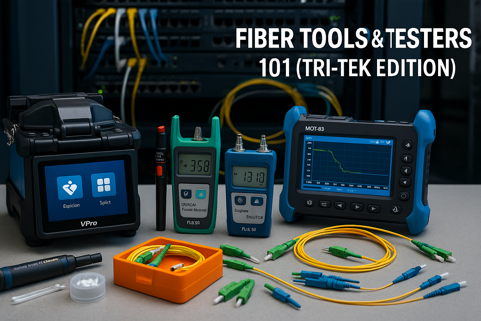
New to fiber or just want a clean, reliable workflow? This guide explains what each tool does and why it matters—from inspection and cleaning, quick fault-finding with VFL/OFI, and accurate loss testing with OPM + light source (FLS-50), to proper prep and fusion splicing (Jonard SPARC and VPro K-Series K5/K3S) and full link verification with OTDRs (Jonard OTDR-1500/OTDR-1000 and VPro MOT-65). Everything is in stock locally at Tri-Tek Electronics, an authorized distributor for the Phoenix metro.
Getting great results with fiber isn’t about having every gadget—it’s about using the right ones in the right order. Below is a practical, step-by-step guide that explains why each tool/tester is important, how it fits into the workflow, and the specific Tri-Tek products—from Jonard Tools and VPro to Platinum Tools, Eclipse, and Pro’sKit—that map to each step.
Tri-Tek Electronics is an authorized distributor. You get genuine gear, full manufacturer warranty coverage, and factory support, with local availability for Phoenix, Mesa, Chandler, Tempe, Gilbert, Scottsdale, and Glendale. Buying locally avoids marketplace counterfeits, incompatible kits, and slow returns—so you finish jobs faster and with fewer surprises.
Why this step matters:
The number one cause of “mystery loss” and intermittent failures is contamination on connector end-faces. A speck of dust or a film of oil can add dBs of loss or cause unstable reflections. If you inspect and clean first, you prevent most rework that chews up labor and schedule.
What to use:
Wireless inspection: Jonard WFM-100 Wireless Fiber Microscope delivers fast pass/fail results on a screen—ideal when you’re up a ladder or in a crowded rack.
Budget inspection: Eyepiece microscopes plus lint-free wipes, swabs, and isopropyl for bench work or smaller kits.
How to do it well:
Inspect every connector you plan to mate. If you see debris or streaks, clean, then re-inspect. If an end-face is scratched or chipped, replace or re-terminate—it will haunt your loss and reflectance numbers later.
Why this step matters:
It’s easy to misdiagnose a bad jumper or a pinched patch as a deeper infrastructure issue. Quick fault-finding prevents needless splicing or panel work.
What to use:
Visual Fault Locator (VFL):
Jonard VFL-150 (bright red 650 nm output) makes breaks, tight bends, and cracked ferrules visibly “glow.”
Value option: Pro’sKit VFL—simple, compact, ideal for basic triage.
Optical Fiber Identifier (OFI):
Jonard OFI-50 clamps over a live fiber and detects traffic/tone without disconnecting anything—perfect for confirming you’re on the correct strand in busy closets.
Key idea:
Use the VFL for short-run physical faults you can see. Use the OFI when you must confirm a live circuit or direction before you touch a patch.
Why this step matters:
Even if nothing is visibly broken, a link can fail because total insertion loss is too high. Measuring loss tells you whether the run will actually carry signal reliably.
What to use (that we stock):
Optical Power Meter (OPM): Jonard FPM-50A (stores references, includes adapters, supports manual offset if your QA requires it).
Value options: Eclipse MT-7615 or MT-7602 for routine checks.
Stabilized Light Source (LS): Jonard FLS-50 (1310/1550 nm) for proper single-mode testing.
How OPM + LS work together (simple, reliable process):
Clean all connectors first—dirty reference cords ruin measurements.
Connect FLS-50 → FPM-50A with a short, known-good reference patch and set your reference (baseline). This “zeros out” your cords so only the link’s loss is measured.
Move the light source to one end of the link and the power meter to the other. Test at 1310 nm and 1550 nm (each sees different bend/absorption behavior).
Record the dB loss values in your closeout packet.
Important:
A VFL is not a light source for loss testing; it’s visible 650 nm and not stabilized. Real loss testing requires a stabilized source at telecom wavelengths (1310/1550 nm).
Why this step matters:
Poor preparation is the root cause of most high splice loss and bad field-connector performance. A great splice starts with a perfect cleave and spotless glass.
What to use:
All-in-one prep: Jonard TK-184 Clean & Prep Kit has strippers, cleaning tools, and a cleaver—ideal for new technicians.
High-precision cleaver: Jonard FC-500 for sub-0.5° cleaves when you want premium splice results.
Good practice:
After stripping and cleaning, inspect the cleaved end (even briefly). If you see chips, angles, or contamination, re-clean and re-cleave. That extra minute saves you from re-splicing later.
Why & when:
Great for patch panels and short drops when speed matters or when fusion isn’t practical. You still need good prep and a clean, perpendicular cleave or you’ll see high loss.
What to use:
We stock LC/SC field-install connectors that pair perfectly with the TK-184 kit. After insertion and lock, verify with OPM/LS.
Why & when:
Best for backbones, campus fiber, security trunks, and any long-term link where reliability and low loss are the priority.
What to use (and how they differ):
Core-alignment, 6-motor splicers (premium performance):
Jonard SPARC SPCO-1
VPro K-Series: K5 Touchscreen 6-Motor Core-Alignment and K3S 6-Motor Core-Alignment
These units actively align the fiber cores for consistently low splice loss, are fast to cycle, and many include conveniences like built-in VFL/OPM, job memory, and large touchscreens.
Clad-alignment splicer (value & speed):
Jonard SPARC SPCL-1
Aligns to cladding—excellent for FTTH and routine field work where a small increase in typical loss is acceptable.
Ribbon splicer:
Jonard SPARC SPRI-1 for mass-fusion of ribbon fiber.
Pro move that saves time at panels:
Use factory-polished LC or SC pigtails and splice them to your field fiber. You get repeatable, low-loss terminations and consistent pass/fail results at the patch panel.
Why this step matters:
An OTDR draws a picture (trace) of the entire run: every connector, splice, bend, or break with distance and loss. It catches hidden problems that a simple loss test can’t—like a mid-span micro-bend or a high-reflectance connector.
What to use (we stock multiple options):
All-in-one touchscreen OTDR: Jonard OTDR-1500 includes OTDR + OPM + LS + VFL + event map + report export—excellent when you want one instrument to test and certify.
Compact OTDRs: Jonard OTDR-1000 for portable, budget-friendly testing; VPro MOT-65 (1310/1550 nm) as a versatile dual-wavelength alternative with integrated utilities.
The connection order (this is crucial):
OTDR → Launch Cable/Box → Cable Under Test (CUT) → Receive Tail (optional).
The launch fiber pushes the OTDR’s near-end “dead zone” out of your way so you can see the very first connector/splice on the CUT.
A receive tail on the far end lets you see the last connector without moving the OTDR to the remote rack.
Test at 1310 nm and 1550 nm. Save SOR/PDF files for documentation.
Choosing launch/receive leads:
We stock OS2 single-mode launch and receive leads with SC/APC and SC/UPC ends in practical lengths (about 300 m for short/access runs and 500 m–1 km for campus/backbone). Most panels are LC, so keep short OS2 SC↔LC jumpers handy to adapt neatly without building a second launch box SKU.
Inspect & clean everything you’ll mate. This alone eliminates most failures.
Quick triage: Use a VFL to chase visible breaks/bends and an OFI to confirm a live strand before moving cables.
Know the numbers: Use OPM + FLS-50 Light Source to measure insertion loss at 1310/1550 nm—but set a reference first with a clean, known-good patch.
Prep like a pro: Strip, clean, cleave, and inspect the cleave.
Terminate or splice: For speed, use field-install connectors; for performance, use a core-alignment splicer (Jonard SPCO-1, VPro K5/K3S). For routine FTTH work, a clad-alignment splicer (Jonard SPCL-1) is a strong value. Prefer pigtails at panels for consistent results.
Characterize the link: Run the OTDR (Jonard OTDR-1500, OTDR-1000, or VPro MOT-65) with a launch and, when you can, a receive lead. Confirm that every event looks right and that total end-to-end loss aligns with your OPM/LS readings.
Save reports and close out with confidence.
Inspect/clean: Jonard WFM-100 (or eyepiece scope), wipes, swabs, isopropyl.
Find faults: Jonard VFL-150 and OFI-50; Pro’sKit VFL for value.
Measure loss: Jonard FPM-50A + FLS-50 stabilized light source; Eclipse MT-7615/MT-7602 for value.
Prep right: Jonard TK-184 kit; FC-500 cleaver for top-tier splices.
Splice: Jonard SPCO-1 (core) or SPCL-1 (clad); VPro K5 and K3S 6-motor splicers; SPRI-1 for ribbon.
Prove it: Jonard OTDR-1500 all-in-one; OTDR-1000 or VPro MOT-65 as compact alternatives—plus OS2 launch/receive leads and SC↔LC jumpers.
Genuine & compatible: Curated kits that fit together—right polish types (UPC/APC), adapters, and firmware paths—so you don’t get stuck in the field.
Full warranty & factory support: As an authorized distributor, we handle the details and you get real coverage.
Local availability: Same-day pickup for the Phoenix metro and quick exchanges if a project pivots—no shipping delays, no returns maze.
Configured bundles: Launch/receive, adapters, and jumpers aligned to the OTDR or splicer you choose—so you leave ready to test.
With the lineup above, you can build, troubleshoot, and certify any single-mode link—from first inspection to final OTDR report—using proven tools we keep in stock.